The swing feeder is an advanced feeding equipment designed to deliver uniform and controlled material flow in industrial applications. Ideal for mining, metallurgy, building materials, and chemical industries, it ensures consistent feeding while minimizing blockages and wear. Its pendulum-like motion allows smooth material discharge with adjustable capacity.
The swing feeder is a robust conveying device typically installed beneath storage bins or hoppers, designed to handle dry, non-caking bulk materials with particle sizes up to 50mm, such as ore, coal, cement, and aggregates. Its operational efficiency and adaptability make it ideal for harsh industrial environments, ensuring reliable performance with minimal maintenance.
Key Features
Uniform feeding without surges or interruptions
Robust construction for durability in tough conditions
Low power consumption for cost-effective operation
Easy maintenance with minimal downtime
Advantages
The swing feeder offers precision feeding control for consistent material discharge, enhanced durability through high-quality steel construction with wear-resistant liners, and exceptional energy efficiency to minimize power consumption and operational costs. Its low-maintenance design ensures easy access for service and repairs, while customizable sizing adapts to diverse production needs. Additionally, its sealed operation effectively reduces dust emissions, enhancing workplace safety and environmental compliance—making it the ideal solution for reliable, efficient bulk material handling.
Swing Feeder Advantages
✔ Precision Feeding – Ensures a steady and controlled material discharge for optimized downstream processes.
✔ Enhanced Durability – Made from high-quality steel with wear-resistant liners for extended service life.
✔ Energy Efficient – Requires minimal power compared to traditional feeders, resulting in reduced operational costs.
✔ Low Maintenance – Simple structure ensures easy access for cleaning and repairs.
✔ Customizable Design – Available in various sizes and configurations to suit different production needs.
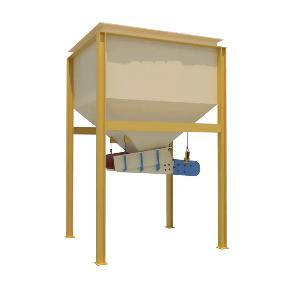
Swing Feeder Structure The swing feeder consists of the hopper, feeding trough, drive mechanism, support frame, etc.
Hopper – Stores and guides material towards the discharge opening.
Feeding Trough (Pan) – Designed with a reciprocating swing motion to regulate material flow.
Drive Mechanism – Comprises an electric motor coupled with a reducer to power the swinging motion.
Support Frame – Provides stability and ensures proper alignment with downstream equipment.
swing feeder structure
Swing Feeder Working Principle The swing feeder is typically installed beneath the discharge opening of a storage bin. Ore falls from the bin’s discharge opening into the ore feeding box. During operation, the motor drives the worm gear reducer via a coupling. An eccentric wheel mounted on the output shaft of the reducer then drives the oscillating base plate of the feeding box in a reciprocating motion, thereby achieving uniform ore discharge. The feeding rate can be adjusted in two ways: by altering the stroke of the eccentric wheel via the calibrated dial on the eccentric disc, or by adjusting the oscillation frequency through the variable-speed motor’s speed.