Home » Equipment » Flotation Equipment » SF Flotation Cell/Machine
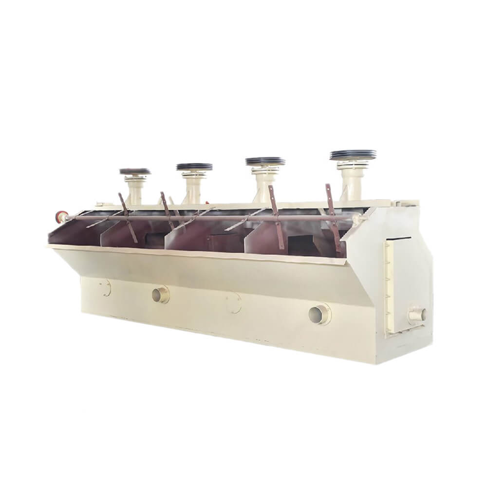
SF Flotation Cell/Machine
Capacity: 0.2~20 m³/min
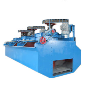
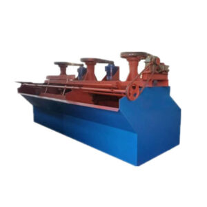
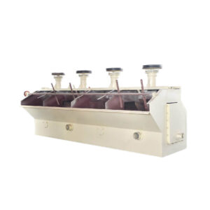
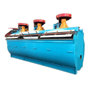
SF flotation cell is a mechanical agitation type with slurry suction and air suction. It represents the third generation of flotation equipment and is widely used in roughing, scavenging, and concentrating operations for nonferrous metals, ferrous metals, and non-metallic minerals. Its simple structure, stable operation, and strong adaptability make it particularly suitable for small and medium-sized mineral processing plants and complex mineral separation operations.
SF Flotation Cell/Machine Overview
Flotation machines constitute the basic equipment for the recovery of useful minerals from non-ferrous ores and other raw materials by flotation. They can also operate as individual flotation cells.
Flotation Cells (Froth Flotation) were developed to separate and recover high-value Sulphide ores from low-grade ore bodies. The Flotation Cell is aerated to produce bubbles and agitated to keep the solids particles in suspension in the pulp. A flotation cell is an appliance in which froth flotation of ores is performed. It has provision for receiving conditioned pulp, aerating this pulp, and for separate discharge of the resulting mineralized froth and impoverished tailings.
Flotation Cells/Machines Types
- Agitating flotation machine
- Self-priming flotation machine
- Aeration flotation machine
- Flotation column machine
Flotation Cells/Machines For Sale
Our froth flotation separation is sold all around the world and is popular with clients. The models of our flotation cells are main including SF, XJK, JJF, XCF, KYF flotation cells.
Advantages
The SF flotation cell delivers high-performance flotation with several key advantages: Its design enables seamless combination with the JJF flotation cell as part of an integrated unit, functioning efficiently as a self-priming suction tank. Equipped with mechanical agitation, self-inflation, and self-priming pulp, it ensures superior slurry mixing while minimizing sanding issues due to upper and lower recirculation—perfect for coarse ore flotation.
Engineered for low energy consumption, it features a wide impeller-to-cover gap, maximizing air intake and bubble dispersion. The backward double-sided impeller blades enhance slurry recirculation for improved particle recovery. With a lower rotor speed, it reduces wear and extends operational life, while the forward-leaning tank design minimizes blind zones, speeding up froth removal for faster separation. The beveled tank geometry ensures stable operation, backed by a proven metallurgical design for reliable performance in demanding mineral processing applications.
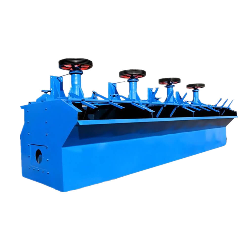
Self-priming Structure
- A special impeller-stator assembly draws air, eliminating the need for an additional blower and reducing equipment investment by 20%-30%.
- The air intake capacity can reach 1.0-1.5 m³/(m²·min), meeting the flotation needs of most minerals.
Optimized Slurry Circulation
- A U-shaped trough with guide plates improves slurry suspension and reduces the risk of sedimentation.
- Suitable for slurries with a concentration of 20%-45%, it achieves excellent separation results for fine-grained minerals (minus 0.074mm).
Energy-Saving and High-Efficiency
- Compared to traditional A-type flotation machines, energy consumption is reduced by 15%-20%.
- Power consumption per unit of processing capacity (based on dry ore) is only 1.8-2.5 kW·h/t.
Flexible Adaptability
Structures & Working Principle
SF Flotation Cell/Machine Structure
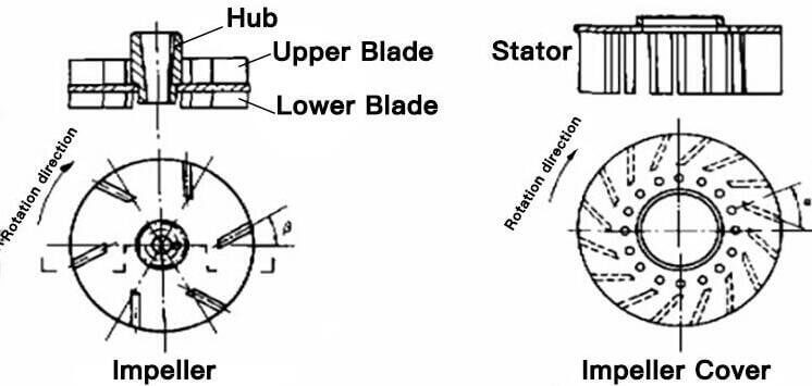
The structure of the SF flotation cell is mainly composed of the tank, impeller, motor, scraper and transmission device, etc.
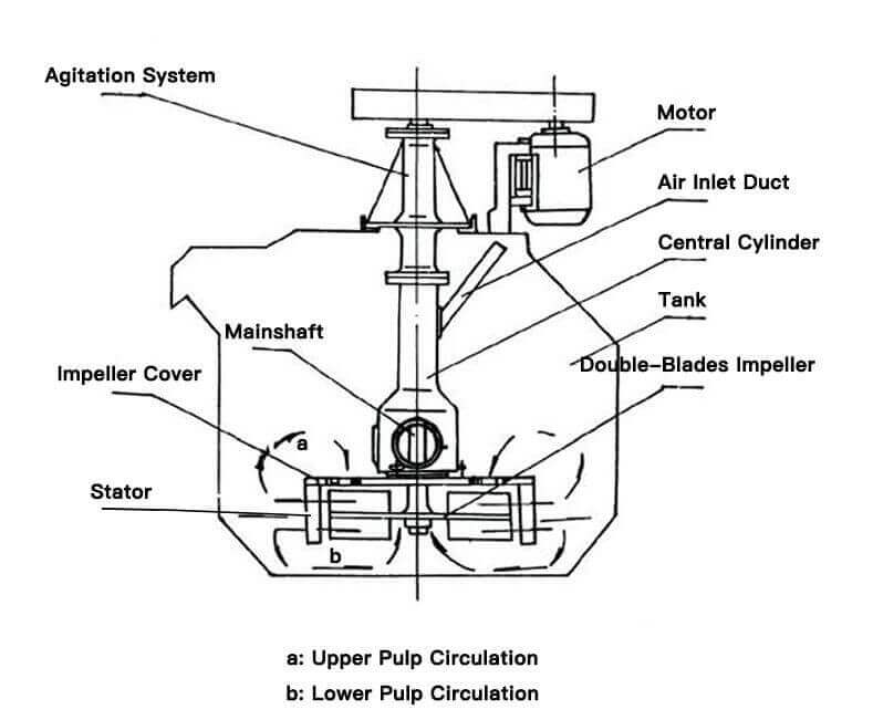
SF Flotation Cell/Machine Working Principle
When the rotor is rotating, an internal vacuum is created both in the upper and lower blade zone. Ambient air is drawn through an air intake pipe and standpipe by the action of the upper blade, the bubbles are then micronized and make the minerals easier to stick on the bubbles. Mineral particles are collected by air bubbles forming aggregates in the contact zone, and Mineralized Bubbles aggregates rise by buoyancy towards the froth zone. The pulp from the upper tank zone is recirculated by the upper blade, while the lower blade is designed to recirculate slurry from the bottom of the tank to minimize the sanding of coarse particles.
Technical Parameters
| Model | Volume(m3) | Cell Size(mm) | Impeller Dia.(mm) | Impeller Speed(r/min) | Capacity(m3/min) | Power(kW) | Singe cell weight(kg) |
| SF-0.37 | 0.37 | 700×700×750 | 296 | 386 | 0.2-0.4 | 1.5/0.55 | 468 |
| SF-0.7 | 0.7 | 820×900×950 | 350 | 400 | 0.3-0.9 | 3/1.1 | 805 |
| SF-1.2 | 1.2 | 1100×1100×1100 | 450 | 312 | 0.6-1.2 | 5.5/1.1 | 1373 |
| SF-2.8 | 2.8 | 1700×1600×1150 | 550 | 268 | 1.5-3.5 | 11/1.5 | 2138 |
| SF-4 | 4 | 1850×2050×1200 | 650 | 220 | 2–4 | 15/1.5 | 2582 |
| SF-8 | 8 | 2200×2900×1400 | 760 | 191 | 4–8 | 30/1.5 | 4129 |
| SF-10 | 10 | 2200×2900×1700 | 760 | 191 | 5–10 | 30/1.5 | 4486 |
| SF-16 | 16 | 2850×3800×1700 | 760 | 191 | 5–16 | 30×2/1.5 | 8320 |
| SF-20 | 20 | 2850×3800×2000 | 760 | 191 | 5–20 | 30×2/1.5 | 9829 |

